. UCM 1 – 3.5 OWNERS MANUAL
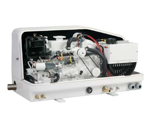
We use brand name components such as Kubota engines, Stamford Newage Markon
generator ends and other high quality components so that our compact design will
fit small spaces. This manual is a general
installation guide only** If in doubt, it is always recommended to consult or
hire an expert. 2 GENERAL SAFETY PRECAUTIONS Please read the entire owners
manual before attempting to install or run your generator set. Safe and proper
operation can only be achieved by following the installation, operating and
maintenance directions laid out for you in this manual. • Electric shock can
cause severe injury, burns or death. Always have qualified electrical servicemen
do any A.C. connection and service work to avoid any possible danger of
electrical shock or damage to other electrical equipment on board. Never perform
electrical work when the Gen-set is running. • Frequently inspect all power
cables and wiring, initially for proper gauge and connection and later for signs
of fraying or deterioration. Remember to use extra caution when handling any
electrical equipment as neglect, misuse or deterioration can cause dangerous or
deadly electrical shock or injury. • NEVER operate the generator set with any
guards or covers removed. • Engine must be completely stopped and fully cooled
down before any maintenance or service can be performed. Hot coolant in an
engine is under pressure. Wear eye protection when performing work on cooling
systems. • Children and pets should be kept away from the generator set at all
times. Loose parts falling into a running engine can be potentially dangerous.
• Never clean your generator set with running water, unit should only be
cleaned when the unit is stopped with a damp rag on outside surfaces only. •
Disconnect battery from Gen-set before performing maintenance and service
procedures. Always wear eye and hand protection while working near or with
batteries. Batteries contain acid and are known to explode. • Inhalation of
exhaust gas can cause personal injury and or death. Make sure adequate
ventilation is provided when running any engine in a confined area. • Fuel and
fumes can be deadly, do not smoke around fuel or while fueling. Always shut off
engines while fueling the vessel. As well as following the directions given in
this owners manual all installations should follow the recommendations of: •
A.B.Y.C. American Boat and Yacht Council • N.F.P.A. National Fire Protection
Association • U.S. Coast Guard Regulations CAUTION Unless your Gen-Set has
been specifically ordered and built as an ignition protection certified unit,
this set must not be installed in gasoline powered vessels, or where any
flammable or explosive gases are present. If your unit is ignition protection
certified, there will be a decal on the starter indicating that the unit is
protected. If you have any doubt, please call Next generation Power at
904-642-8555 3 Do’s: • READ SAFETY INSTRUCTIONS AND ALL OTHER CHAPTERS IN
THIS MANUAL • Allow 500 hours of exercise workload to break in the new engine.
(60-85% load is recommended) • Regular maintenance of fluids and filters. Oil
& filters are cheap, engines are not. • Keep fluids filled to their proper
levels. Oil that is down 1/3 quart is too low! • Periodic inspection of wires,
hoses, and belts for abrasion or wear. • Keep your gen-set clean from salt,
dirt, oil, fuel and general debris • Replace worn hoses and belts immediately.
Do not wait for breakage. • Use proper mix of anti-freeze coolant NOT to
exceed 45% ethylene glycol. • Keep a maintenance journal to record routine
service intervals • Use proper replacement parts as noted in this owners
manual • Ensure that fuel tanks on vessel remain at least 1/3 full to prevent
air intake of the generator fuel system. • Generally keep gen-set loads
between 50-90% as much as possible • Use the glow plug for 10 seconds before
starting the engine. Don’t’s: • DO NOT start the generator under an
electrical load. Turn OFF all air conditioners, stove top elements, microwaves
etc.. before starting the set. You may resume appliance load after the engine is
running. • DO NOT overload the gen-set by turning on too many appliances at
the same time. Calculate your appliance wattage consumption to stay within the
generator output limits or budget between electric appliances back and forth if
necessary. Heat loads are big users of power. Check your appliance labels for
power requirement ratings. DO’s and DON’T’s 4 • DO NOT USE ETHER-YOU
WILL RUIN THE ENGINE AND VOID THE WARRANTY. • DO NOT immerse the generator in
water, oil or cleaning materials • DO NOT operate the gen-set without an air
filter cartridge • DO NOT use synthetic oil until at least 500 hours of engine
break in under a good load is complete. • DO NOT adjust throttle speed
linkage. The frequency of the generator Hz is factory set to correspond with
proper engine RPM and the pulley drive system. Lowering or raising the engine
speed will cause drastic voltage output changes that can damage appliances. •
DO NOT attempt any repairs unless you are a qualified technician • DO NOT
allow any storage of containers, fuel, tools, etc.. around the generator set
during operation. • DO NOT leave genset in a state of dirty condition. Fuel
and grease may cause premature wear of rubber engine mounts. Debris should be
vacuumed or blown out with compressed air and periodically cleaned with a mild
degreaser and very light water mist. (Avoid water in the generator windings) •
DO NOT hold the glow plug in for more than 10-15 seconds. If you hold it in
longer, you will burn out the glow plug. • DO NOT authorize any warranty
repair work by third party repair facilities unless first obtaining consultation
and approval by Next Generation Power Engineering Inc. Unauthorized repair bills
will be denied. DO’s and DON’T’s (Continued) 5 GENERAL SAFETY PRECAUTIONS……………………………………………….
3 Do’s and Don’ts……………………………………………………………………….
4-5 UCM 1-3.5 Specifications…………………………………………………………….
7-8 General Layout Front View…………………………………………………………..
9 General Layout Side View / Belt Side View…………………………………………
10 Dimensions…………………………………………………………………………….
11 Selecting a Location……………………………………………………………………..
12 Mounting………………………………………………………………………………..
13 Ventilating…………………………………………………………………………..…
14 Sound Proofing………………………………………………………………………….
15 NextGen Sound Proof Enclosure………………………………………………………
16 Fuel System……………………………………………………………………………
17 Cooling System………………………………………………………………………….
18 Exhaust System…………………………………………………………………………
19 Vernalift Installation…………………………………………………………………….
20 D.C. Electrical…………………………………………………………………………
21 A.C. Electrical………………………………………………………………………
22-25 Initial Start Up Procedure……………………………………………………………
26-27 Maintenance…………………………………………………………………………28-29
Load Testing…………………………………………………………………………….
30 UCM 1-3.5 Parts……………………………………………………………………….
31 Electrical D.C. Wiring Diagram………………………………………………………..
32 Troubleshooting………………………………………………………………………33-36
INDEX 6 Type……………………………………………..………Horizontal,
water-cooled 4 cycle engine # Of Cylinders………………………………………………………………………………………………1
Bore & Stroke (in.).……………………………………………………………..………….2.95
x 2.76 Displacement (cu. In.)……………………………………………………………….…………….18.86
SAE net Intermittent (HP/rpm)……………………………………………………..……….7/2800
Combustion system……………………………………………………………………………Spherical
Compression ratio…………………………………………………………………………………….23:1
Fuel Injection Pump type………………………………………………………..Bosch
‘mini’ type Nozzle type……………………………………………………………………..…..Bosch
throttle type Cooling System………………………………………………..……Fresh
Water Heat Exchanger Lubricating system…………………………………….Forced
Lubricating by Trochoid pump Fuel……………………………………………………………………..ASTM
#2 Diesel or equivalent Lubricating Oil…………………………………..…..Quality
Better than API service CC class Fresh Water Capacity………………………………………………………………………….1.2
Quart Lubricating Oil Capacity……………………………………………………..………..1.0
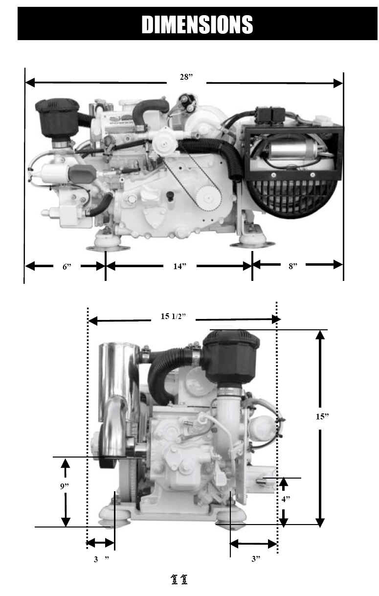
U.S. Quart Measurement (L x W x H)…………………………………………………….……..28”
x 15” x 15” Dry Weight (Lbs.)…………………………………………………………………………………160
lbs. Starting System………………………………………………………………………..12
Volt Battery Charging System…………………………………………………………………………………….None
Fuel Line Diameter…………………………………………………………………………..…….5/16”
Fuel Return Line Diameter……………………………………………………………………..1/4”
Raw Water Diameter……………………………………………………………………..………..5/8”
Exhaust Diameter…………………………………………………………………………………..1
_” Output Voltage…………………………………………………………………………………120/240
Output Amps…………………………..…………………………………………………………….30/15
Output Watts………………………………………………………………………..….3.5Kw
or 3500 UCM 1-3.5 SPECIFICATIONS 7 60 Hz Rating………………………………………………………………3.5
k.w. 3.5 KVA 1.0 P.F. 50 Hz Rating………………………………………………………………3.5
k.w. 3.5 KVA 1.0 P.F. Voltage Frequency Regulation………………………………………………………………………
+ 5% Recommended Battery Size………………………………………………………….….100
A.H. or Larger Total Air Required………………………………..…………………………………………………150
CFM Fuel Pump Lift Maximum…………………………………………………………………….………3
Feet Water Pump Lift Maximum……………………………………………………………………….…….4
Feet Cooling Water Flow………………………………………………………………..……
3.0 Gal. Per/Min Fuel Consumption Maximum……………………………………………………………….
.40 Gal/Hr. Fuel Consumption Average………………………………………………………………….
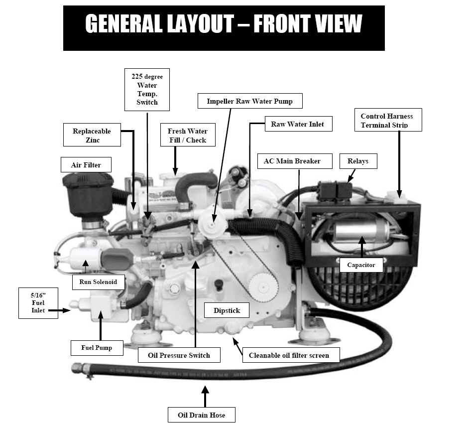
.20 Gal/Hr. UCM 1-3.5 SPECIFICATIONS (Con’t) 8 FIGURE 1 Air Filter Replaceable
Zinc Cleanable oil filter screen Oil Drain Hose 225 degree Water Temp. Switch
Fresh Water Fill / Check 5/16” Fuel Inlet Dipstick Relays Run Solenoid Fuel
Pump Oil Pressure Switch AC Main Breaker Control Harness Raw Water Inlet
Terminal Strip Impeller Raw Water Pump Capacitor GENERAL LAYOUT – FRONT VIEW 9
FIGURE 2 GENERAL LAYOUT - side view 1 _” Diameter Exhaust _” Diameter Fuel
Return Coolant Drain Glow Plug 5/16” Fuel Supply Inlet FIGURE 3 GENERAL LAYOUT
- Belt side view Exhaust Mounting Flange Taper Bushing Pulley Mounting Plate
Page 10 Fuel pump DIMENSIONS 11 4” 9” 3 _” 3” 15” 15 1/2” 28” 6”
14” 8” The following factors should be considered before selecting the
location where your Gen-set will be installed. PROXIMITY TO LIVING QUARTERS •
If several locations are available it is advisable to install the set furthest
away from living sleeping quarters to keep noise levels in these areas to a
minimum. DRYNESS OF LOCATION • Keep the Gen-set from under outside hatches
where water (especially salt water) may drip or splash. • If a location under
a hatch is chosen, provisions should be made to divert any water away from the
set. If a damp location is the only option a sound shield may be advisable to
keep as much moisture away from the set as possible. REMEMBER WATER AND
ELECTRICITY DO NOT MIX. VENTILATION • Air must be available to the Gen-set for
both combustion and generator cooling, therefore you should try to select a spot
that already has adequate air flow or where inlet and exhaust fans can be
installed. PLUMBING • Consideration must be given to fuel, raw water, exhaust
and electrical connections SERVICING • Unit must be accessible for regular and
long term maintenance. SPACE • There must be enough space around all sides of
the set for movement on the isolation mounts. One to two inches on all sides
with extra room on the front side for maintenance would be the minimum required.
All of the above factors should be considered before deciding on the permanent
location of your gen-set. Keep in mind while selecting your location that the
easiest place to install the set may not be the best long-term home for the
unit. It is always better to spend more time routing the plumbing etc initially
than to select an easy spot where the unit can’t be serviced later, or is
under a leaky hatch where it will rust away. In most cases where space permits
the engine room is usually the best place for a gen-set as it usually has
adequate ventilation, access to plumbing, sound proofing, etc 12 SELECTING A
LOCATION Due to wide variations in boat styles and designs, it is impossible to
give a complete description of any one particular installation. Following are
guidelines to which one may follow to achieve an acceptable and safe
installation. The UCM1-3.5 is of a very rugged design incorporating roller main
bearing and a pressurized oil delivery system. As such the set may be placed in
any direction and position in the vessel as long as it will not be run at an
angle of more than 30 degrees continuously. No matter where the unit is placed
it must be securely attached to a platform, rails or stringers. If a flat
relatively level platform is not available, one should be constructed out of a
minimum ” thick marine grade plywood or ” aluminum plate. Base must be
lagged, bolted or glassed securely to the stringers. Through bolting is the best
way to secure the isolators to the base, 5 16” diameter stainless steel bolts
with large washers should be used. If you have a wood base and do not have
bottom access for through bolting , 5 16” diameter stainless steel lags with
large washers may be used. If at all possible when lag bolting a unit in place,
try to align as many mounts over the stringers as possible so that extra long 2”
or 2 ” lags secure the mounts through the base to the stringers. A spot of
silicone or marine caulking on the lag bolts works well in sealing moisture out
of wood where lags penetrate. Some isolator mounting bolts may be hard to reach
once the set is in place, if so the following procedure is very helpful. 1.
Position generator set in exact desired location on platform with mounts rotated
for easiest access. 2. With a pencil or marker trace around as much of the four
mounts as possible including mounting holes. 3. Lift Gen-set back out of
location and remove the four isolation mounts by loosening the center nuts on
mount studs. 4. Using one of the mounts as a template you can finish marking any
of the 8-mount holes that could not be marked with the unit in place. 5. Bolt or
lag the mounts to the base as already discussed, (mounts are not attached to the
Gen-set at this time.) 6. Gen-set may now be lowered back onto mount studs and
center nuts replaced and tightened. NOTE: All 8 mounting holes must be used. ie;
two lags or bolts per mount If you wish to lift the Gen-set by rope or chain, a
convenient lifting spot is the starter mount plate. To use this mount plate you
must first remove the belt guard and starter as follows: 1. Using a Phillips
head screwdriver, remove the rectangular belt inspection plate mounted on the
top of the belt guard. 2. Working through the inspections hole using a 14 mm
socket or wrench, remove the two starter mount bolts. 3. Disconnect all wires on
the starter and slide it out front of the mount plate. Lift belt guard off of
Gen-set. Using a rope or chain attached to the starter mount plate, you now have
a Sturdy lifting point to hoist the set into place. Once the set is in place you
can replace all components by reversing the removal order. MOUNTING 13 As
previously mentioned, the Gen-set needs air for both combustion and for the
generator winding cooling. By far generator cooling requires the most air
(approx.125-150 CFM) and since it is not consumed it must be evacuated from
around the set. If the Gen-set is installed in a reasonably sized engine room
with good natural airflow, it is possible that no blowers or fans need to be
used, especially while the vessel is in motion. It is possible for excessive
temperature to be reached in the same engine room under various conditions, such
as in very hot climates, when vessel is not in motion, or when main engines are
running while Gen-set is running, etc The only sure way to know if there is
adequate air flow is to monitor engine room temperature on a hot day under
various operating conditions. Temperature should be checked near the black
plastic air inlet of the generator and should not exceed 140 degrees Fahrenheit.
If the Gen-set is to be installed in a smaller separate enclosure or
compartment, an opening of 25-35 square inches is needed to admit air in. This
combined with a blower fan of 125-150 CFM or more to force air out is required.
It is best to have the air inlet near the black plastic air intake or the
generator with the evacuation fan being on the far side of back wall of the
compartment. In general we are trying to draw cool air into the compartment near
the air inlet end of the generator to cool the window, than draw the air over
the Gen-set and out the opposite end. The blower fan may be a 12- volt D.C. unit
operated off of a switch or could be a 120 volt A.C. unit connected directly up
to the output of the generator. A 120 Volt A.C. model running off of the
generator would of course start and stop automatically. It has been our
experience that the more expensive squirrel cage style blowers are far quieter
in operation the axial type units. CAUTION - IF YOU ARE INSTALLING IN A GASOLINE
POWERED VESSEL ALL ELECTRICAL COMPONENTS MUST BE IGNITION PROTECTION CERTIFIED.
14 VVENTILATION For those wanting the ultimate in quiet performance, Next
Generation Power offers an optional sound dampening fiberglass enclosure that
offers excellent noise suppression for the UCM 1-3.5. The enclosure also offers
limited splash protection from liquids. This does not mean it is a waterproof
enclosure, since it was designed more for noise reduction. If space limitations
allow for the added enclosure dimensions, you will find the sound enclosure a
worthwhile investment. Proper ducting is required to allow for airflow in and
out of the enclosure to maintain proper cooling of the windings. The enclosure
has clever design elements for the attachment of fuel lines, return lines, power
cord, battery cable and control harness entry points. In some vessels, critical
space requirements may not allow for the addition of an enclosure, in this case
consideration may be given to using sound dampening materials with appropriate
venting and ducting to accomplish the task of reducing noise. When a set is
placed near living quarters or under floorboards, a reduction in noise may be
found by remote mounting an air intake silencer as far away as possible using
flexible intake hose. Consult Next Generation Power for our recommendation on
this. SOUND PROOFING 15 FIGURE 5 16 Fresh Air flow INLET GRILL Blower fan HOT
AIR EXHAUST NEXT GEN SOUND PROOF ENCLOSURE 5/16” Fuel IN _” Fuel Rtn.
Coolant Overflow Mounting Brackets Raw Water IN Blower Fan 1. Battery Negative
2. Battery Positive 3. A/C Main Power Cord 4. Control Harness FIGURE 4 The fuel
filter supplied is a fine 2 micron secondary filter and must be used in
conjunction with a customer supplied 20-30 micron primary filter separator. All
filters should be mounted in a spot that is easy to access for servicing. Make
sure to leave enough room below the filter bowl for easy draining and changing
of filters. If possible it is best to use a separate fuel pickup for the Gen-set
as well as a dedicated primary filter. This generally will eliminate fuel
starvation problems due to suction created by other engines running off the same
fuel supply. When it is not feasible to run a separate fuel pickup and filter,
it may be possible to use a second fuel outlet on a main engine primary filter.
If you do this, both the main engine, and Gen-set should be carefully monitored
after initial installation to determine that fuel starvation is not happening.
Fuel starvation would show up as a loss of speed and frequency on the Gen-set
and would typically happen during high load conditions. A minimum of 5 16”
diameter marine diesel approved fuel line, should be used from the primary
filter to the secondary filter, and from the secondary filter to the barbed fuel
inlet fitting on the fuel pump. ( see figure 2 ) ” diameter fuel line is to be
used for the return line and runs from the fitting on the injector shown in Fig.
2 back to the top of the fuel tank. Fuel return must be returned to the tank and
not tied back into the fuel system as air will be re-circulated and cause
intermittent shut down. Very little fuel is actually returned at very low
pressure. Return fuel line can run uphill with no problem. NOTE: Most initial
run problems and intermittent shut down situations are due to fuel supply leaks
introducing air into the system, even small amounts of air will cause erratic
running or immediate shut down. All fittings should be double-checked for
tightness, fuel pickups should be inspected and hose clamps secured. Always use
hose clamps of the correct size, too large of a clamp reduced to a very small
size will not remain completely round and air leaks will result. HINT: When
there is excessive lift or a long run from the fuel supply tank to the Gen-set,
there is a small possibility of fuel starvation and a greater chance of air
entering the fuel system. If you have a situation such as this a secondary fuel
pump mounted near the fuel tank pushing fuel to the set will help cure this
situation. FUEL SYSTEM 17 The UCM 1-3.5 is a completely marinized, fresh water,
heat exchanger cooled machine. The unique feature of this package is that the
engine is designed to be cooled by natural convection circulation of the fresh
water. This system is very simple and reliable eliminating several maintenance
items such as the fresh water pump, drive belt, thermostat, hose etc Fresh water
anti-freeze mix is added to the engine through the cap at the top of the heat
exchanger tank. Mixture should just cover the heat exchanger tubes leaving ” 3
8” of space for expansion. In warm climates we recommend approximately 30
anti-freeze and 70 water mix. If you are operating in cold climates where you
have danger of freezing, up to 50 antifreeze may be used. If more than 50
anti-freeze is used, overheating will almost always result. Excess water may
flow out of the overflow tube located below the pressure cap, this is normal and
should only happen during the first warm up after filling. A coolant catch can
be used to keep this excess coolant from getting into the bilge. Because of the
convection cooling design you can see operating temps of 170 degrees to 210
degrees F. These engines are very thermally stable and can be run at
temperatures up to 230 degrees F. Raw water is circulated through the heat
exchanger and out the exhaust by a belt driven self-priming pump located at the
front top- side of the unit. ( see figure 1.) A clean constant supply of raw
water must feed the pump, generally via a through-hull, sea-cock, and sea
strainer. Raw water supply fitting is 5 8” diameter so a through hull and
strainer of ” or larger is fine. NOTE: All raw water hose fittings and clamps
should be of an approved marine grade with all connections double clamped. Any
bad connections or loose clamps could cause flooding and sinking of the vessel.
If the top of the heat exchanger is less than 10” above water line there is a
danger of water siphoning through the raw water pump into the exhaust. This must
be corrected by installing an anti-siphon valve or siphon brake into the raw
water plumbing. The easiest place to install the siphon brake is between the raw
water discharge on the heat exchanger and the raw water inlet of the exhaust
mixer. The factory piece of hose is removed and the siphon brake installed
according to the manufacturer of the brake. Usually the siphon brake is mounted
18-24” above the water line to be effective. COOLING SYSTEM Scoop type water
pickups should never be used as water will be forced through the pump and into
the exhaust system while the vessel is in motion. This is very dangerous as the
exhaust will eventually fill and raw water will back up into the engine through
the exhaust valve. Catastrophic failure will result as soon as the engine is
re-started. 18 The water-cooled stainless steel exhaust mixer is 1 ” OD and
should be used in conjunction with a water lift exhaust muffler and 1 ” I.D.
approved marine grade exhaust hose. All connections must be double clamped. It
is possible to run the UCM 1-3.5 without a water lock providing he entire
exhaust system runs down hill. Exhaust noise without a waterlock muffler will be
markedly higher as well. The best results as far as noise level is concerned are
achieved by using a water-lock muffler and running the exhaust system out
through the transom 2-3 inches above waterline. We have seen systems run up to
20 feet of 1 ” I.D. hose with no back pressure problems. There are many
different brands and styles of water-lock, or water-lift mufflers available that
will work fine. At times your choice may be based on physical size or inlet
outlet arrangements. We at Next Generation Power have had excellent results
using the heavy-duty fiberglass units made by “CENTEK”. Because of the low
exhaust outlet on the UCM 1-3.5, CENTEK model ( 1500018) works very will as it
has a low side inlet with top outlet. Top inlet with top outlet versions are
also available (model 1500001). Most exhaust situations are shown in the
following diagrams supplied by CENTEK. The most important consideration is that
the exhaust run down hill into the water-lock muffler so that exhaust flooding
does not occur. EXHAUST SYSTEM 19 VERNALIFT INSTALLATION 20 The UCM 1-3.5 uses a
very simple 12-volt D.C. system for starting, running and shutdown systems.
Consideration must be given to battery charging as the set does not have any
battery charging capacity at all. Most installations simply use a house or main
engine battery for starting, when the generator is running an AC battery charger
is used. While the Gen-set is in operation it uses 3-4 amps of 12- volt D.C.
current to operate the fuel solenoid and fuel pump. Battery cable size should be
determined by length of run but usually 4-gauge is adequate. Battery positive is
connected to the top lug on the starter solenoid shown below. Battery negative
may be connected to any convenient stud or bolt connected to the engine above
the isolation mounts. Negative wire connected to jumper wire shown below. The
remote panel wiring harness is color-coded and should be connected to the
connection terminal strip block shown below. Ten and twenty or 30 foot extension
harnesses are available from Next Generation Power. D.C. ELECTRICAL A C output
Fitting D.C. Remo te Termi nal Block OIL SWITCH SOLENOID THROTTLE LINKAGE WATER
SWITCH BATTERY POS. CONNECTI ON FIGURE 6 NEGATIVE (-) BATTERY CONNECTIO N FIGURE
7 21 FKD JL FIGURE 8FI View showing A.C. connection points A.C. ELECTRICAL
CONNECTION Breaker screw is “Hot” Neutral and Ground Attaches to Bolt here
22 Screen cover screws • All A.C. electrical connections should be made by a
licensed and qualified marine electrician. STANDARD 120 VOLT 60 Hz OUTPUT Unless
otherwise specified the UCM 1-3.5 is manufactured using a standard four wire
capacitor regulated brush-less generator. Standard wiring is 120V 60 Hz output.
Access to the A.C. output connections is made by first removing the two
stainless steel screws holding the screen cover in place. (See Fig 8. ) The “Hot”
leg (usually the black wire) of the vessel should be connected to the unused
output terminal of the breaker. Ground and neutral wires (usually the green and
white) should be connected to the neutral ground bolt shown in Figure 8. CAUTION
Many vessels are either built or have had changes made to the wiring where
standard colors are not used and do not match colors mentioned above. If this is
the case a licensed marine electrician must be consulted to determine proper
connection of wires. A.C. ELECTRICAL WIRING Windi ng Windin g TO LOAD 120V 30
amp Breaker Ground / Neutral Connection U 1 U 2 U 4 This Diagram also applies to
optional Voltage Regulated Generator U 3 23 REWIRE TO 120/240 VOLT 60 Hz UCM
1-3.5 may be rewired for 120 240 Volt use with the addition of an external
customer supplied 2-pole 15 amp breaker. To rewire, you must gain access to
output leads as explained under 120 volt 60Hz output section and then disconnect
the four numbered wires that went to the breaker and the ground lug. Leads
numbered 2 and 3 should be paired together and attached to the ground neutral
lug. Lead 1 is one of the hot legs and lead 4 becomes the second hot leg. The
two hot legs should now be run to a remote two pole 15 amp 240 volt breaker.
Factory 30 amp single pole breaker is NOT used in this configuration. If the
Gen-set is to be installed in a gas powered vessel the Gen-set must be an
ignition protection certified unit and the breaker used must also be Ignition
Protection Certified. Windi ng Windi ng U2 U3 U1 U4 Ground N eutral Lug Line One
to Load Line Two to Load Fact ory 30 amp Bre ake r Not Used Customer Supplied
Remote Breaker 15 amp 240V 2-pole This diagram also applies to optional voltage
regulated machines 24 OPTIONAL 50 HZ 240 VOLT OUTPUT If your UCM 1-3.5 was
factory ordered as a 50 Hz 240 volt unit it will be wired as per the following
diagram. Connections may be made as per directions under standard 120 volt 60 Hz
output. U4 U2 U3 Winding Winding “Hot” Leg to Load Connection Taped Off 15
Amp 240V Breaker U1 Neutral Ground Lug 25 • INITIAL CHECKS AND OPERATIONS
Check oil and water levels Double- check all electrical connections to make sure
they are correctly positioned and secured. Rock Gen-set back and forth on its
mounts one final time to make sure the unit is not hitting anything and to be
sure that all hoses and lines will have adequate slack to allow Gen-set to move.
Turn Off the main and all auxiliary breakers on the vessel’s panel. Open
generator sea-cock and fuel shutoff valves if any. • PRIMING THE FUEL SYSTEM
The fuel pump may be energized by jumping the 12 gauge red wire on the remote
panel connector block to the 14 gauge yellow wire. You should hear the fuel pump
working and fuel will flow back to the return on the tank. Run the pump for
approx. 2-3 minutes allowing time for the fuel system to completely fill with
fuel. Remove jumper wire. • STARTING Preheat the glow plugs for 10-15 seconds
at the remote panel and then crank the unit over. Generator should start up
within 5-10 seconds. If not, stop for a minute and try again. Often on initial
cold starts the set will run for a few seconds and then stop. This is normal as
the oil pressure has not yet built up to override the oil pressure shutdown
switch. Unit should remain running on second or third attempt. If the set starts
and runs for a bit or stumbles and runs slowly, you will have to re-prime the
system, as air in the fuel lines is likely to be the problem. INITIAL START UP
PROCEDURE CAUTION: If the unit does not start after several cranking attempts or
one to two total minutes of cranking, there is a danger of filling the exhaust
system with seawater. (This may lead to serious engine damage). Close seacock or
remove water pump drive belt to prevent further water from being pumped into the
exhaust and proceed to trouble shooting section. 26 As soon as the set is
running, inspect the machine for signs of fuel, water, or exhaust leaks as well
as unusual noises or smells. If any problems are noted, the set should be shut
down immediately until problem is corrected. While checking for leaks etc., you
should also check to make sure there is water exiting the exhaust through-hull
indicating the raw water pump is working and that the engine is actually getting
the cooling water. Shut unit down if you do not see water flow within 1 minute
of startup. 27 • All Gen-sets or engines should be visually checked frequently
during their first 5-10 hours of operation for leaks, loose wires, loose
fittings etc • Following is a chart showing the various maintenance items and
intervals that should be attended to, to keep your machine running at peak
performance for the longest possible time. ACTION REQUIRED DAILY MONTHLY or 100
Hrs 6 Months or 250 hrs YEARLY Or 750 hrs Inspect the set X Check Oil Level X
Check Coolant Level X Check Fuel Level X Change Oil Clean Filter X Drain
Sediment from Fuel Filter X Check Zinc Anode X Check Air Filter X Change Fuel
Filter X Check Water Pump Drive Belt X Change Water Pump Drive Belt X Change Air
Filter Element X Initial oil change should be done after the first 30-50 hours
of run time. 1. INSPECT THE SET Visually inspect the machine for leaks, loose
connections, loose clamps, frayed wires etc 2. CHECK OIL LEVEL Pull out the
dipstick and make sure that the level is at or near the top mark. 3. CHECK
COOLANT LEVEL Remove the heat exchanger fill cap and make sure the level of
coolant is just above the cooling tubes. Add coolant mixture if needed. 4. CHECK
FUEL LEVEL Make sure main or auxiliary tank has enough fuel for intended run
time. Running out of fuel will require rebleeding of the fuel system. 5. CHANGE
OIL CLEAN FILTER Oil should be drained by removing the cap off the drain hose
located under the generator. (See figure 1). A 3 8” diameter oil resistant
drain hose slipped over the drain valve fitting makes this job much cleaner and
easier. After the oil is drained, close the drain valve and remove the cleanable
oil filter shown in Figure 1, by unscrewing the nut on the MAINTENANCE 28 (
MAINTENANCE - Continued – ) filter. The screen type filter may be cleaned in
fuel or a degreasing cleaner. Oil the filter and threads and then re-install.
Fill crankcase to the fill level on the dipstick with approved diesel grade oil.
6. DRAIN SEDIMENT FROM FUEL FILTER Water and sediment should be drained from the
filter bowl by unscrewing the black drain valve located on the bottom of the
bowl. 7. CHECK ZINC ANODE Using a 5 8 wrench unscrew the zinc to determine how
much of it is left. Zinc should be replaced if it is less than 1 3 of its
original size. Rate of decomposition varies from vessel to vessel, but after
several inspections rate may easily be determined. 8. CHECK AIR FILTER Air
cleaner element may be inspected by unscrewing the top of the filter canister
lid. Visually check the element for blockage, rips, tears or excessive moisture
of element material. Replace if needed. 9. CHANGE FUEL FILTER Change the filter
as per supplied Racor instructions. 10. CHECK WATER PUMP DRIVE BELT Visually
check the belt for signs of cracking or fraying, change if needed. Check the
belt tension by pressing lightly in the middle of the belts span. It should not
deflect more than ” under the pressure. Tighten if needed by loosening the two
pump hold down bolts and sliding pump slightly forward. 11. CHANGE PUMP DRIVE
BELT Remove old belt by sliding belt off of lower pulley first and then lifting
it off of the top pulley. Install the new belt by wrapping around top pulley
first and then sliding it around lower pulley second. Using this procedure it
may not be necessary to readjust belt tension. 12. CHANGE AIR FILTER ELEMENT
Change element as described under “checking air filter” 29 Once the
generator set is running with no leaks or problems, you should determine that
the output voltage is correct, either by gauges on the vessel or by a hand held
meter. If using a hand held meter you can test voltage at a convenient
receptacle after turning the appropriate breaker on. If the voltage is in the
acceptable range., you may begin to test load. Start by turning on one breaker
at a time on the vessels panel beginning with non-critical loads such as a
toaster, stove element etc All devices should be checked one at a time at first
for correct function and then in groups to determine what may be run together
without overload. The UCM 1-3.5 will provide 30 amps of current at 120 volts. If
this is exceeded, overload will result and unit will lose speed, frequency and
voltage. A sure sign of overload is black smoke coming out of the exhaust.
Typically the UCM 1-3.5 will carry an air conditioner up to 16,000 BTU’s along
with a typical battery charger, some lights, t.v. and have 1- 1 Kw left over for
another appliance such as a microwave, stove element etc • Gen-sets should be
visually checked frequently during the first 5-10 hours of operation for leaks,
loose wires, loose fittings etc LOAD TESTING 30 Air Filter Mann & Hummel
C630 (call NextGen) Raw Water Pump Jabsco 51510-9001 Impeller Kit Jabsco
22405-0001 Pump Drive Belt Goodyear 190XL037 Zinc Standard 3 8 NPT Pencil Type
Fuel Pump Facet 40 105 Pump to Heat Exch. Hose Gates 18746 Heat Exchanger Champ
2005187 CP Exhaust Mixer Next Generation Power Call Next Gen Racor 2 micron fuel
filter Racor R12S Shutdown Solenoid Synchrostart 1753ES Oil Pressure Switch
Nason SM-2A-10F-ATVT Water Temp. Switch Nason TM-2B-225 RAT Generator Capacitor
Generic 400V 40UF Main Drive Belt Goodyear W800 Eagle PD Base Engine Kubota
EA300 NB Generator (Standard Model) Markon BL105E UCM 1 – 3.5 QUICK REFERENCE
PARTS Parts Dept. Hours of Service Monday Friday 8 a.m. 5 p.m. EST
1-904-642-8555 ngpower bellsouth.net 31 Red 14 White 14 Red 14 Yellow w/ Black
14 Red 14 Red 14 Red 12 Yellow 12 Red 12 Blue 14 Red 12 Yellow 14 Yellow 14
White 14 Solenoid Starter OIL SWITCH 87 86 Relay RUN SOLENOID WATER SWITCH
Battery Fuel Pump One Switch Remote with Indicator Light Black 14 Ground Red 14
Blower fan Yellow 14 Ind. light Yellow 12 Glow/stop Red 12 Battery Blue 14 Crank
Black 14 87A 86 UCT 1-3.5 Wiring Diagram Red 14 32 TROUBLESHOOTING UNIT DOES NOT
CRANK Bad battery or low voltage Bad Battery cables or faulty wiring between
Gen-set and remote panel Bad Rocker switch Bad starter POSSIBLE CAUSE DIAGNOSIS
OR REMEDY Make sure battery is in good condition and is fully charged. Charge or
replace as required. Check all wiring and connectors with a multimeter. Repair
wire or cable as req’d. Test switch with a multimeter for proper operation.
Replace if needed. Feed 12 volts + directly to the cranking spade connection on
starter (blue wire). Set should crank, if not, remove starter and have tested by
a qualified technician. Replace starter if required. UNIT CRANKS BUT DOES NOT
START Air in fuel system No preheat Run solenoid not pulling in Bleed air as
instructed under initial start up procedures. Unit must be preheated for 10-20
seconds before every cold start. Faulty wire or connections from remote switch.
Test to be sure 12 volt + is getting to glow plug. Glow plug itself may be
faulty, remove from engine and test with 12V + and replace if needed. The run
solenoid must pull in or the unit will not start. While cranking gently push the
solenoid linkage in. If the linkage pulls in and holds you may have a weak
battery or bent and binding linkage. Charge battery and retest or check for
sticky or binding linkage. 33 UNIT CRANKS BUT DOES NOT START Run solenoid not
pulling in (Con’t) Clogged air intake Clogged Exhaust System Make sure 12 volt
+ is getting to the white wire on the solenoid while cranking. If not
troubleshoot as required. If 12 volt + is getting to the white wire on the
solenoid and the solenoid does have a good ground assume the solenoid is faulty
and replace. Unit must have air to run, if the machine has a plugged air intake,
unit will not run. Unit will not run with a clogged or collapsed exhaust system.
Typical symptoms will be popping back through intake system. POSSIBLE CAUSE
DIAGNOSIS OR REMEDY UNIT STARTS BUT IMMEDIATELY STOPS Solenoid NOT holding in If
the solenoid drops out as soon as you quit cranking, the unit will stop. Test
the solenoid by feeding 12 volt + to the red hold wire while pushing the
solenoid plunger into the fully retracted position. Solenoid should remain in
the retracted position even after manually releasing the plunger. If the
solenoid drops out after 12 volt is applied and manual tension is released, we
assume that it is bad and replace. If the solenoid is o.k., we assume that 12
volts is not getting to the solenoid. First, make sure that the engine does have
oil and that it is not overheating. If oil and water are o.k., we assume that 12
volts is not getting through the oil or water switches. These switches should be
tested one at a time by jumping across the switches terminals while attempting
to start the machine. If the unit remains running while a switch is jumped and
it quits when not jumped we have found the bad switch. Do not rule out the
possibility of two bad switches or faulty wiring and connections feeding the run
circuit. 34 Air in fuel system Bad oil or water switch Faulty wiring The number
one reason why the set would shut down is air in the fuel system. All fittings,
hoses, clamps, filters, pick-up tubes etc. should be double checked to make sure
absolutely no air is entering the system. When in doubt disconnect the entire
fuel system and run the machine out of a small fuel supply with short hoses for
a period of time to determine if the vessel’s fuel system is at fault. Jump
switches as previously discussed under “solenoid not holding” in but you may
have to leave the switches jumped for longer periods of time to determine if you
have an intermittently bad switch. Inspect all wiring carefully for loose
terminals or loose screws that may vibrate and cause intermittent shut down.
Correct as required. UNIT RUNS BUT SHUTS DOWN INTERMITTENTLY POSSIBLE CAUSE
DIAGNOSIS OR REMEDY UNIT WILL NOT SHUT OFF Solenoid stuck in Throttle
misadjusted Bad shutdown relay Check for jammed solenoid or linkage. Free up or
replace as required. If the unit almost stops but chugs along slowly the
throttle stop screw may have to be turned in slightly. If the shutdown relay
does not energize the run circuit when stop position is activated, the relay is
most likely at fault. 35 NO OUTPUT VOLTAGE Breaker tripped Faulty capacitor
Generator problem The circuit breaker will trip if the unit is overloaded or
short- circuited. The breaker may also trip if the Gen-set is working to
capacity in a very hot environment. In any case with a breaker tripping, it is
advisable to determine the cause before restarting. It is possible to have a
faulty capacitor causing loss of output voltage but this can only be tested by
replacing the capacitor and restarting. Consult the Markon generator handbook or
consult with Next Generation Power. WRONG OUTPUT VOLTAGE Faulty generator Engine
speed problems Troubleshoot out of Markon Generator Handbook. Generator output
voltage may be changed slightly by adjusting the engine speed up or down. This
is done at the speed linkage shown on Fig. (shortening linkage increases the
speed) Speed is factory set and tested. We do not recommend changing the speed
unless you have an A.C. frequency meter to determine how much you have changed
output frequency. 36 DATE HOURS SERVICE PERFORMED SERVICE INTERVAL RECORD 37