Search Results
|
|
   |
Portable Generators | Standby Generators | Air Compressors | UPS Uninterruptible Power Sources | Automotive Parts
| ||||||||||||||||||||||||||||||||||||||||||||||||||||||||||||||||||||||||||||||||||||||||||||||||||||||||||||||||||||||||||||||||||||||||||||||||||||||||||||||||||||||
Guardian | Guardian Elite | QuietSource | Commercial | Specs | Transfer Switches | Pricing
FEATURES Liquid Cooled Gas Engine Generator Sets - Not available at this time, please see Model numbers 5210, 5212, 5219, 5221 and the California Emissions model 40 kW 4626.
Continuous Standby Power Rating Models:
15kW 60 Hz 05054 (15kW/Single Phase NG or LPV)
20kW 60 Hz 05053
(20kW/Single Phase NG or LPV)
25kW 60 Hz 05040 (25kW/Single Phase
NG or LPV)
Generac UL Listed Transfer Switch Options Available for models 05054, 05053 & 05040
UL 2200 Listed CSA Listed Power
Matched 2 Year Limited Warranty Naturally Aspirated
Transfer switch is not included with these models.
| INNOVATIVE DESIGN & PROTOTYPE TESTING are key components of GENERAC’S success in “IMPROVING POWER BY DESIGN.” But it doesn’t stop there. Total commitment to component testing, reliability testing, environmental testing, destruction and life testing, plus testing to applicable CSA, NEMA, EGSA, and other standards, allows you to choose GENERAC POWER SYSTEMS with the confidence that these | SOLID-STATE, FREQUENCY COMPENSATED VOLTAGE REGULATION. This state-of-the-art power maximizing regulation system is standard on all Generac models. It provides optimized FAST RESPONSE to changing load conditions and MAXIMUM MOTOR STARTING CAPABILITY by electronically torque-matching the surge loads to the engine. | ||
| systems will provide superior performance. TEST CRITERIA: >PROTOTYPE TESTED | SINGLE SOURCE SERVICE RESPONSE from Generac’s dealer network provides parts and service know-how for the entire unit, from the engine to the smallest electronic component. You are never on your own when you own a GENERAC POWER SYSTEM. | ||
| >SYSTEM TORSIONAL TESTED >ELECTRO-MAGNETIC INTERFERENCE >NEMA MG1-22 EVALUATION | � | GENERAC TRANSFER SWITCHES. Long life and reliability are synonymous with GENERAC POWER SYSTEMS. One reason for this confidence is that the GENERAC product line includes its own transfer systems and controls for total system compatibility. | |
GENERATOR SPECIFICATIONS
TYPE ....................................................................... Four-pole, revolving field
ROTOR INSULATION ....................................................................... Class F
STATOR INSULATION ...................................................................... Class H
VOLTAGE WAVE FORM DEVIATION .................................................... <5%
TOTAL HARMONIC DISTORTION (line to line) .................................... <3%
TELEPHONE INTERFERENCE FACTOR (TIF) ..................................... <50
ALTERNATOR ................................................. Self-ventilated and drip-proof
BEARINGS (PRE-LUBED & SEALED) ....................................................... 1
COUPLING .................................................................... Direct, Flexible Disc
LOAD CAPACITY (STANDBY) ............................................................. 100%
NOTE: Emergency loading in compliance with NFPA 99, NFPA 110,
paragraph 5-13.2.6. Generator rating and performance in accordance
with ISO8528-5, BS5514, SAE J1349, ISO3046, and DIN6271 standards.
EXCITATION SYSTEM
DIRECT .................................................................. DC excitation system -
Low-velocity brushes and slip rings -
VOLTAGE REGULATION ........................................................ Solid-state -
�1% regulation -
GENERATOR FEATURES
-Four pole, revolving field generator, directly connected to the engine
shaft through a heavy-duty, flexible disc for permanent alignment.
-Generator meets temperature rise standards for class �F� insulation as
defined by NEMA MG1-22, while the insulation system meets the
requirements for the higher class �H� rating.
-Stator windings are �trickle� varnished and rotor windings are �roll-dipped�
for complete impregnation.
-Unit tested for motorstarting ability by measuring instantaneous voltage
dip with a waveform data acquisition system.
-All models utilize an advanced wire harness design for reliable interconnection
within the circuitry.
-Magnetic circuit, including amortisseur windings, tooth and skewed stator
design, provides a minimal level of waveform distortion and an electromagnetic
interference level which meets accepted requirements for standard AM radio,
TV, and marine radio telephone applications.
-Voltage waveform deviation, total harmonic content of the AC waveform,
and balanced T.I.F. (Telephone Influence Factor) have been evaluated to
acceptable standards in accordance with NEMA MG1-22.
-Alternator is of drip-proof guarded construction.
-Fully life-tested protective systems, including �field circuit and thermal
overload protection� and standard mainline circuit breakers capable of
handling full output capacity.
-System torsional acceptability confirmed during prototype testing.
ENGINE SPECIFICATIONS
MAKE ............................................................................ FORD INDUSTRIAL
MODEL ............................................................................................... 2.5FG
CYLINDERS ..................................................................................... 4 in-line
DISPLACEMENT ........................................................ 2.5 Liter (153 cu. in.)
BORE ............................................................................. 96.01 mm (3.78 in.)
STROKE .......................................................................... 86.36 mm (3.4 in.)
COMPRESSION RATIO ...................................................................... 9.37:1
INTAKE AIR ................................................................... Naturally Aspirated
NUMBER OF MAIN BEARINGS ................................................................ 5
CONNECTING RODS .................................................... 4-Drop forged steel
CYLINDER HEAD ........................................................................... S.O.H.C.
PISTONS .......................................................................... 4-Aluminum Alloy
CRANKSHAFT ................................................................ Drop Forged Steel
VALVE TRAIN
LIFTER TYPE .................................................................... Rocker Arm Type
INTAKE VALVE MATERIAL ......................... High Temperature Alloy Forged
EXHAUST VALVE MATERIAL ..................... High Temperature Alloy Forged
VALVE SEATS ........................................................................... Replaceable
ENGINE GOVERNOR
- ELECTRONIC.............................................................................. Standard
FREQUENCY REGULATION, NO-LOAD TO FULL LOAD ............ 0.5%
STEADY STATE REGULATION .................................................. �0.25%
LUBRICATION SYSTEM
TYPE OF OIL PUMP ............................................................................ Gear
OIL FILTER ...................................................................... Full flow, cartridge
CRANKCASE CAPACITY .................................................. 3.8 Liters (4 qts.)
COOLING SYSTEM
TYPE OF SYSTEM ........................................ Pressurized, closed recovery
WATER PUMP .......................................................... Pre-lubed, self-sealing
TYPE OF FAN ................................................................................... Pusher
NUMBER OF FAN BLADES ....................................................................... 6
DIAMETER OF FAN ......................................................... 406 mm (16.0 in.)
FUEL SYSTEM
FUEL
- Natural Gas or L.P. Vapor .......................................................... Standard
CARBURETOR ............................................................................ Down draft
SECONDARY FUEL REGULATOR - Nat. Gas or L.P. Vapor Systems
AUTOMATIC FUEL LOCKOFF SOLENOID ................................... Standard
OPERATING FUEL PRESSURE VAPOR SYSTEMS ..Nat. Gas 5 to 14� H2O
LP Vapor.....11� to 14� H2O
ELECTRICAL SYSTEM
BATTERY CHARGE ALTERNATOR ................................... 15 Amps at 12 V
STARTER MOTOR .................................................................................. 12 V
RECOMMENDED BATTERY ............... 12 V, 525 CCA @ 0o F/75 A.H., 26R
GROUND POLARITY ..................................................................... Negative
Rating definitions - Standby: Applicable for supplying emergency power for the duration of the utility power outage. No overload capability is available for this rating. (All ratings in accordance with BS5514, ISO3046 and DIN6271). Maximum wattage and current are subject to and limited by such factors as fuel Btu content, ambient temperature, altitude, engine power and condition, etc.
| STANDBY | ||||||
| GENERATOR OUTPUT VOLTAGE/KW - 60Hz | HS-15 | HS-20 | HS-25 | |||
| NG/LP | Rated AMP | NG/LP | Rated AMP | Rated NG/LP AMP | ||
| 120/240V, 1-phase, 1.0 pf | 15 | 62.5 | 20 | 83.3 | 25 104.2 | |
| MOTORSTARTING Maximum at 35% instantaneous voltage dip with standard alternator; 60 Hz | 29 KVA | 38 KVA | 50 KVA | |||
| FUEL Fuel consumption – 60 Hz – 100% Load | N.G. | L.P. | N.G. | L.P. | N.G. L.P. | |
| ft.3 /hr. (gal./hr.) m3 /hr. | 236 NA 6.68 | 92 2.53 2.6 | 307 NA 8.69 | 122 3.35 3.45 | 375 150 NA 4.12 10.62 4.25 | |
| COOLING Coolant capacity System lit.(US gal.) Engine lit.(US gal.) Radiator lit.(US gal.) Coolant flow/min. 60 Hz lit.(US gal.) Heat rejection to coolant 60 Hz BTU/hr. Cooling air flow 60 Hz m3/min. (cfm) COMBUSTION AIR REQUIREMENTS Flow at rated power 60 Hz m3/min. (cfm) | 11.4 (3.0) 5.3 (1.4) 6.1 (1.6) 67.8 (17.9) 66,000 963 (4200) 1.4 (50) | 11.4 (3.0) 5.3 (1.4) 6.1 (1.6) 67.8 (17.9) 88,000 963 (4200) 1.8 (64) | 11.4 (3.0) 5.3 (1.4) 6.1 (1.6) 67.8 (17.9) 110,000 963 (4200) 2.1 (75) | |||
| EXHAUST Exhaust flow at rated output 60 Hz m3/min. (cfm) Max. recommended back pressure Kpa (Hg) Exhaust temp. at rated output °C (°F) Exhaust outlet size N.P.T. (female) | 3.4 (120) 5.0 (1.5”) 449 (840) 1.5” | 4.8 (168) 5.0 (1.5”) 516 (960) 1.5” | 5.9 (210) 5.0 (1.5”) 566 (1050) 1.5” | |||
| ENGINE Rated at RPM 60 Hz HP at rated KW 60 Hz Piston speed 60 Hz m/min. (ft./min.) BMEP (PSI) 60 Hz | 1800 26 310 (1020) 76 | 1800 34 310 (1020) 99 | 1800 43 310 (1020) 125 | |||
| POWER ADJUSTMENT FOR AMBIENT CONDITIONS Temperature -1.65% for every 10°F above - °F Altitude -3% for every 1000 ft. above - ft. | 77 600 | 77 600 | 77 600 | |||
| SOUND OUTPUT In dB(A) at 23 feet with generator operating at full load | 69 | 71 | 71 |
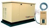
| STANDARD ENGINE & SAFETY FEATURES Home Standby - 15, 20 & 25 - High Coolant Temperature Automatic Shutdown - Battery Charge Alternator - Low Coolant Level Automatic Shutdown - Battery Cables - Low Oil Pressure Automatic Shutdown - Battery Tray - Overspeed Automatic Shutdown (Solid-state) - Vibration Isolation of Unit to Mounting Base - Crank Limiter (Solid-state) - 12 Volt, Solenoid-Activated Starter Motor - Oil Drain Extension - Air Cleaner - Radiator Drain Extension - Fan Guard - Factory-Installed Cool Flow Radiator - Control Console - Closed Coolant Recovery System - UV/Ozone Resistant Hoses - Stainless Steel Flexible Exhaust Connection - Secondary Fuel Regulator (N.G. and L.P.) - Rubber-Booted Engine Electrical Connections - Flexible Fuel Line - Fuel Lockoff Solenoid - Critical Exhaust Silencer - Isochronous Governor - Battery Trickle Charger - Weather Protective Enclosure (Locking Type) - Main Line Circuit Breaker |
Home Standby Control Features: - Home Standby Control Console - Manual/Auto/Off switch - Six light LED indicator for - generator status and - fault status - Fuses (panel overload) - Set exercise time switch Home Standby Microprocessor Controls - Automatic voltage regulation - Utility voltage sensing - Utility interrupt delay - (10-second setpoint) - Engine warm-up - (10-second setpoint) - Engine cool-down - (1-minute setpoint) - Seven-day exerciser |
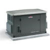
15 kW UNIT WEIGHT: 1023 lbs. [29.94"]
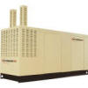
Home Standby - 15kW Home Standby - 20kW Home Standby - 25kW Generator Sets
Sitemap | Website Design by Search Engine First Place


